
here's some more pics as to where to the pipes all go.Originally Posted by catmando

Thread: Post Engine Pics
Results 181 to 200 of 247
-
 Charter Member

- Join Date
- Oct 2008
- Location
- Dallas, TX
- Posts
- 1,642
11-10-2008 01:19 AM
-
Charter Member

- Join Date
- Oct 2008
- Posts
- 452
11-10-2008 01:35 AMMore
pat WUnique Innovative Drivetrain Solutions
-
Registered

- Join Date
- Nov 2008
- Location
- West end of Lake Erie(K.I or bust)
- Posts
- 77
11-10-2008 07:01 AMHey, wheres the L.E.P. stickers Originally Posted by FULL FORCE
-
Charter Member
- Join Date
- Oct 2008
- Location
- Dallas, TX
- Posts
- 1,642
11-10-2008 11:16 AMthanks, cool stuff you get to hang around and build! Originally Posted by shifter

-
Charter Member

- Join Date
- Oct 2008
- Location
- Cleveland/Marblehead, Ohio
- Posts
- 991
11-10-2008 08:01 PMThey do not fit the valve covers!! Originally Posted by LAKE EFFECT
35 Cigarette Mistress
-
Charter Member
- Join Date
- Oct 2008
- Posts
- 452
11-14-2008 02:57 AMFound some more pics.
SOOOooooooooo many projects, I need to learn how to scan so I can put up some oldies.
pat WUnique Innovative Drivetrain Solutions
-
Charter Member
- Join Date
- Oct 2008
- Posts
- 452
11-14-2008 03:05 AMmore
pat WUnique Innovative Drivetrain Solutions
-
E Dock

- Join Date
- Nov 2008
- Location
- E-Dock Baby
- Posts
- 260
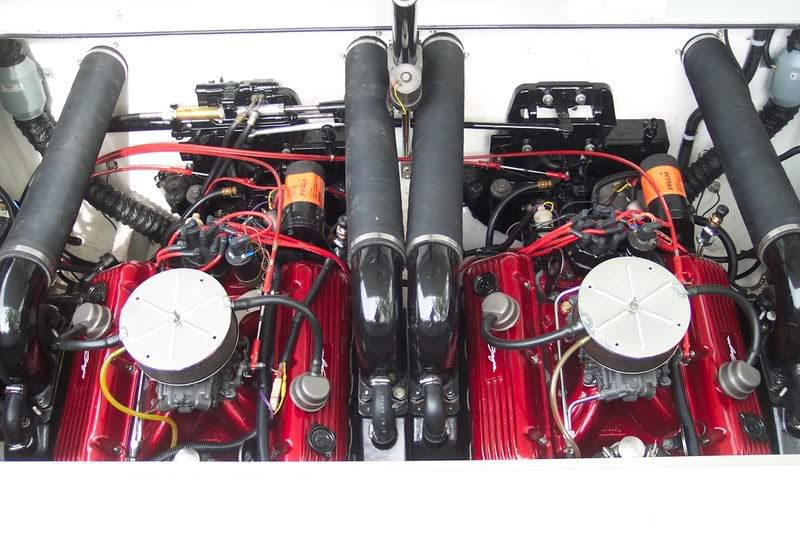
11-14-2008 12:50 PMThe Cary's engine room.
-
Charter Member

- Join Date
- Oct 2008
- Location
- Mississippi
- Posts
- 350
11-14-2008 02:09 PM Originally Posted by saxman
vacuum pump
-
Charter Member
- Join Date
- Oct 2008
- Location
- Mississippi
- Posts
- 350
11-14-2008 02:17 PM Originally Posted by shifter
is it going or coming
Pat is that something you all made?
-
Charter Member

- Join Date
- Oct 2008
- Location
- Tulsa, OK/GLOC
- Posts
- 4,285
11-14-2008 02:54 PMThat is one crowded engine room....... Originally Posted by rbhudelson

-
Registered

- Join Date
- Nov 2008
- Location
- Fond du Lac, WI Cheeseheads & Kiekhaefer Scarab KV Miami Vice LTD Formally Snap-On Tools Canada
- Posts
- 4,453
11-14-2008 03:42 PMNo doubt. Probably has more $ tied up in the spare props then I do in my motors. Originally Posted by Sea-Dated
-
Infamous

- Join Date
- Nov 2008
- Location
- Arlington, Tx.
- Posts
- 510
11-14-2008 11:19 PMAwesome! How much beam? The 50' Nor-Tech(which I've seen four motors in) is only 9'. Originally Posted by rbhudelson
-
E Dock
- Join Date
- Nov 2008
- Location
- E-Dock Baby
- Posts
- 260
11-15-2008 12:25 AMI didn't know Nortech put 4 in the V. Originally Posted by catmando
The beam on the Cary is 14.6.
-
Charter Member
- Join Date
- Oct 2008
- Posts
- 452
11-15-2008 02:35 AMStrip Poker 388
That is all us.
The engines are facing flywheel to flywheel with a U-shape transmission and a Z shape transmission. The offset transmissions are FNR and they send the driveshafts to the rear, under the the headers to the 6-speeds, and then the drives.
I designed the brackets for the serpentine belt to mount the sea pump and the powersteering pump. The arrangement is different for the front motor and the rear (no power steering) Flipped the intakes, Mefi 4 controllers and cable throttle body. Very stock engines. The engine complete with headers, steel engine mounts, bellhousing, clutch, offset transmission = 624 lbs.
We wanted to have the engines as low as possible. They are counter rotating because they are flywheel to flywheel. I picked the LS7 for the power to weight ratio. We are looking at several other engines to go with our transmissions and drives. So far these are hard to beat.
pat W
Unique Innovative Drivetrain Solutions
-
 So you think you have a big diesel?
Registered
So you think you have a big diesel?
Registered

- Join Date
- Nov 2008
- Location
- So.Calif.
- Posts
- 28
11-15-2008 04:42 AMThe World's Biggest Combustion Engine.
-------------------------------------------------------------------------
The worlds biggest engine is the Wartsila-Sulzer RTA96-C. It is a turbo charged two stroke diesel engine and it is the most powerful and efficient low revolution engine in the world today.
The Wartsila-Sulser is manufactured by the Aioi Works in Japan and is part of Japans Diesel United Ltd engine manufacturers.
Below is an 89 foot long 44 foot wide 12 cylinder engine, literally as big as a house ! What I find confusing is why they haven't actually built the ship around the engine ? How they actually get the 2000 ton engine out of the plant and moreover install an engine of this size into a ship makes the mind boggle.
These large engines are designed to power the worlds super oil tankers and large container ships. They are built to the ship owners preferences. They usually request an engine construction of a single unit and single propeller design for ease of maintenance, and not surprisingly any later troubleshooting. A single unit and single screw design has also proved over time to have a longer life span than double or even quad screws.
These engines are built in 6, 8, 10, 12 and 14 cylinder configurations. All the engines are straight or 'inline'. The diameter of each cylinder is 3 foot 2 inches with a stroke of 8 foot 2 inches. The 12 cylinder version weighs in at 2000 metric tons and delivers 90,000 Horse Power at 100 Revs per minute, with best fuel economy at 53,244 HP at 90 Rpm.
When I mention economy, the 14 cylinder engine for example with a displacement of 25,480 Liters ( 1.56 million cubic inches ) burns up 1,660 gallons of crude ("bunker") oil every hour.
-------------------------
The Mathematical calculation : 1,660 gallons/per hour = 39.5 barrels of crude oil/used per hour = $2,844. These figures are worked out from the basis of crude oil @ $72 a barrel*.
$2,844 every hour the engine runs or 27.6 Gallons which is $46.00 every minute or 76 cents a second ! That is of course if the ships buy oil at trade price...if not then these figures are the absolute minimum.
( * at time of publishing )
-------------------------
In the image below a worker at the plant is finalizing work on the cylinder block. This image shows the piston sleeves. The worker could quite easily have a nap inside one of the bores and no one would notice !
Below are the pistons that will soon be fitted into the engine. Unlike normal car sized pistons these 3 foot diameter pistons incorporate lots of holes and it is through these holes that oil is injected through valves to keep all the working parts at a maximum low wear tolerance. Despite the colossal amounts of power output produced by these engines, surprisingly low wear rates have actually been recorded. Cylinder liner wear for example is only about 0.03 mm down for every 1000 hours of engine use.
It must be remembered here that these engines work at about 20 times slower than a normal 2.0 Liter car engine and this is a major contributor to the life of the engine.
The image below depicts the 300 ton crankshaft of the 10 cylinder engine. You may notice here that there are steps on the wall of the casing to climb down into the engines sump !
In the image below the pistons shell bearings are being fitted into the engine block. They are lowered into place by a crane and guided in by two workers and a supervisor. They keep all surfaces of the engine clean at this stage as any grit or dirt could later add wear to the engine or worse destroy it, so the workers are wearing special cloth overshoes so as not to leave any abrasions on the fine working surfaces. Also you may notice that sheeting is covering the rest of the engines crankcase bearing housing to keep the dust off. These engines cost many millions upon millions of dollars; in fact, more than the ship itself that they are installed into.
100,000 HP was actually achieved on a test bed in the workshop with the 14 cylinder model, running the engine flat out at just under 102 RPM.
102 Rpm may sound slow compared to a normal sized car engine that operates at about 2-4000 rpm, but when an engine is as big as this then fast engine revolutions are made obsolete by the sheer power output.
-
So you think you have a big diesel? (Part II)
Registered
- Join Date
- Nov 2008
- Location
- So.Calif.
- Posts
- 28
11-15-2008 04:44 AMThree of the pictures didn't make the last post. Check them out!
-
Founding Member / Super Moderator


- Join Date
- Oct 2008
- Location
- West Michigan
- Posts
- 37,359
- Blog Entries
- 44
11-15-2008 08:24 AMHoly Crap. Originally Posted by shifter
Well, the next challenge could be 4 Ilmors.
-
Charter Member
- Join Date
- Oct 2008
- Location
- Dallas, TX
- Posts
- 1,642
11-15-2008 02:47 PMDid Nigel Hooks Scarab run a similar setup? Originally Posted by shifter
-
Charter Member

- Join Date
- Oct 2008
- Location
- Long Island,New York
- Posts
- 70
11-15-2008 03:57 PMReggie built a 40 race boat with the inline setup
JC PERFORMANCE ENGINES
ON THE CHIP RACING
2006,07 National Champions


Posting Permissions
- You may not post new threads
- You may not post replies
- You may not post attachments
- You may not edit your posts